power system design
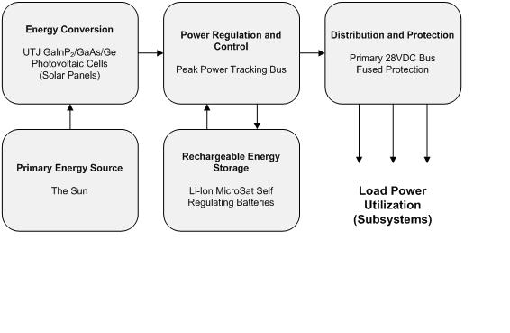
All system components of the Crescent Comms lunar mission are heavily dependent upon one another. Power systems are no exception. For example, an increase in power consumption from an added high-power-amplifier for the communications system could result in additional solar panels and power management electronics, which in turn will increase mass, which may increase the size of the rocket, which may dramatically and prohibitively increase the cost of the entire mission. Because of this, the process of designing the power system for this specific mission was a very iterative process. A typical power system with the Googol decisions for each block can be seen in the diagram below. The discussion following, attempts to justify these design selections.
Load Power Utilization
The first consideration in any power system is to determine the load requirements. Below is a table showing the estimated power consumption of each system onboard the Googol vehicle.
Subsystem |
Power Needed (W) |
Comments |
|||||||||
Communications System (Total) |
100 |
Minimum Sustainable Power from Communications Engineers |
|||||||||
Attitude Keeping Equipment |
20 |
||||||||||
Radar Altimeter |
16 |
||||||||||
CPU |
5 |
||||||||||
Propulsion System |
10 |
Ignition Source |
|||||||||
Mechanical System |
25 |
Solar Panel Actuators and Motors |
|||||||||
Losses and Other Overhead |
20 |
I2R Losses, Amplifiers, etc. |
|||||||||
Total |
196 |
|
From this analysis, it was determined, that a continuous minimum power output of 200 W would be needed to sustain all operations onboard the vehicle.
Primary Energy Source
The second design consideration of the power system was determining the primary energy source. Compared to most satellites, the mission duration for Crescent Comms is very short at no longer than 3 weeks planned from launch to rover support conclusion. Therefore, power system options like nuclear reactors and radio isotope systems were quickly ruled out due to their extremely expensive cost and their primary applicability to interplanetary and deep-space missions. The mission was long enough to use a renewable energy source, because primary batteries alone would not supply enough power for 3 weeks without loading down the vehicle with hundreds of batteries.
Therefore, the solar PV-battery system was chosen and hence the Sun became our choice for the primary energy source. It provides a scalable amount of power with added solar panels while more than sufficing the mission duration requirements.
PV Energy Conversion
When choosing solar cells, many factors must be considered. However, our main focus was to decrease weight which would have the largest impact on the cost of the mission. Therefore, fewer very high efficiency solar panels were chosen over a higher number of lower efficiency panels.
We chose Spectrolab to manufacture the solar cells and panels. Not only are their solar cells specifically designed for the space environment, Spectrolab is the world leader in providing space-based solar arrays. Because the duration of the mission is relatively short, radiation degradation effects of the solar cells were not accounted for. At the expense of an increase in price to achieve a higher efficiency and thus decreased weight, Spectrolab’s most efficient cells to date were chosen (28.3% beginning of life (BOL) efficiency): ultra triple junction (UTJ) GaInP2/GaAs/Ge solar cells. The datasheet for these solar cells can be found at http://www.spectrolab.com/DataSheets/TNJCell/utj3.pdf. Several of these cells in series and parallel will create a solar panel.
From Patel’s Spacecraft Power Systems (2005), a good rule of thumb for determining the optimum system voltage is the following equation:
Optimum System Voltage = 0.025 * power requirement
Since our power requirement is >200 W, we should have an optimum system voltage of 5VDC. However, with this small of a voltage, the current will be relatively large and will increase the diameter requirement for the onboard conductors distributing the electricity. Therefore, the lowest common system spacecraft voltage of 28VDC was chosen for the Googol bus voltage.
Because 28V will be the bus voltage from which all accessories will run and the battery recharging circuits require a voltage greater than 28V, the voltage output of the solar panels should be slightly higher. The Voc of each solar panel should be 32 V to account for this. In addition the Isc of each panel should be 200W / 32V / 2 panels in parallel, which results in 3.125 A.
Spectrolab specifies a panel output of 330 W/m2 for these solar panels. If we assume a very conservative end of life (EOL) 24% efficiency with this configuration under Air Mass 0 conditions (1.353 kW/m2), and a poor sun incident angle of 40o, this yields approximately 1 m2 of solar cells to maintain 212 W/m2. Therefore, we will order 2 panels at 1.5 m2 each to yield a maximum output at these conditions of 636 W/m2.
Rechargeable Energy Storage
The trip to the lunar surface will last approximately 3.5 days where the vehicle will experience a one hour long eclipse of the sun by the Earth, and several shorter eclipses of the sun by the moon. Once Googol has landed on the moon, the sun will be in full view for the next 26 days without interruption. A solar PV-battery system suits this type of mission very well by charging the batteries and running system power strictly from the solar panels during times when the sun is in view, and operating the vehicle strictly from battery power when an eclipse is taking place.
We chose Li-ion MicroSat batteries from Saft Batteries Inc. Again, these batteries are space-proven and come as a self regulating module. Therefore, there is no need to include the added weight and cost of a charge/discharge (C/D) module in the power management and distribution (PMAD) system. These batteries will have a capacity of 16.8 Ah and a nominal energy level of 480 Wh. This power is enough to sustain operations on the vehicle for more than two hours of darkness.
Power Regulation and Control
There are three main types of power system architectures: sun regulated, fully regulated, and peak power tracking. The peak power tracking is suitable for large variations in solar array input energy and maintains a constant voltage on the bus. Since we have sensitive instruments attached to this bus, such as the radar altimeter, the bus voltage should be held as constant as possible. The sun regulated architecture is a cost effective solution, but relies on the output of the solar panels to dictate the voltage on the bus. Fully regulated solutions are more expensive, complex, and well suited for high power requirements (>2kW). Therefore Crescent Comms will use a peak power tracking regulation and control system. A schematic of this architecture can be seen below.
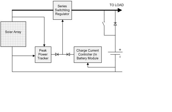
In this architecture, the Series Switching Regulator reduces the output solar panel voltage to the desired 28VDC level. In addition, it is always removing power from the array to increase efficiency, since solar panels decrease in efficiency when they are heated.
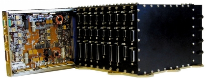
This architecture will be accomplished by Terma’s PMAD system for science missions. It is specifically designed for smaller research applications like ours and is meant for peak power tracking power systems. In addition, thermal dissipation will be handled by this system as well and will be transferred to the spacecraft structure. The datasheet for this system can be found at http://www.terma.com/multimedia/PMAD_Flyer3.pdf. A general photo of this module can be seen in the following figure.
Distribution and Protection
The protection mechanisms in the power system are in place to protect the power system from internal faults or load faults. Each main subsystem circuit will be separately protected with fuses. When, a fault does occur, the fuse will be blown quickly to reduce damage to the system. Therefore, the battery will be used during this instant to dump current into the fuse to blow it as fast as possible.